prototype pcb assembly flying needle online testing technology
date:Jul 10,2019
Return listprototype pcb assembly flying needle online testing technology
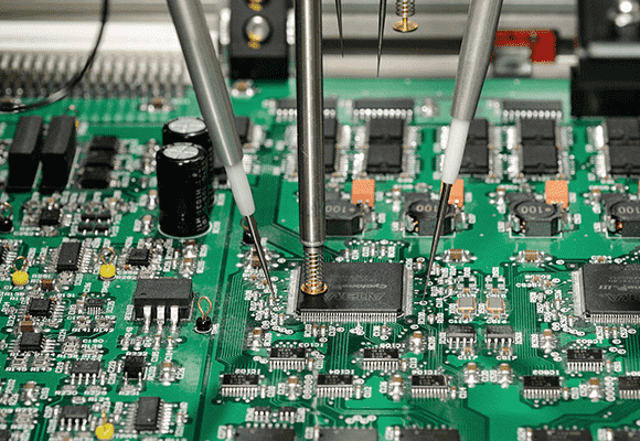
For prototype pcb assembly circuit board that cannot be tested with a needle bed, a flying needle type in-line tester can be used. According to the pre-programmed coordinate position program, the test probe is moved to contact with the test point, and each test probe performs an open/short test forprototype pcb assembly component according to the test procedure during the test operation.

The flying needle type online tester is equipped with a plurality of needles, each of which is mounted at an appropriate angle, and the test dead angle phenomenon does not occur, thatomnidirectional angle test can be performed. Therefore, the usageof the flying needle online tester can greatly improve the prototype pcb assembly defectivedetection rate.
The test procedure of the flying needle type online tester is generally generatedautomatically. The method is: theprototype pcb assembly circuit CAD system is connected with the test equipment to form a data link station, and the position coordinates of the CAD data output are transformed into the probe coordinates, and then the node data, prototype pcb assemblycomponent data production test procedures. CAD data convert into test programsdirectlycan significantly shortenprogramming time and read cycle time and reduce operating costs.
(1)prototype pcb assembly label positioning. The probe produced by the CAD data are connected to the coordinates, and the coordinate correction is performed by prototype pcb assemblyimage recognition with the help ofthe wiring reference marks on the printed circuit board, thereby reducing the prototype pcb assemblymanufacturing error of the circuit board to be tested and the setting error of the prototype pcb assemblycircuit board, so thatachieving high accuracy measurement.
The principle of image recognition and position correction of the referencelabel is: thereference label printed on the prototype pcb assembly circuit board wiring when the CCD camera reads the coordinates, the center coordinate of the mark is extracted by the image processing device, and the offset from the reference coordinate is calculated. Then, the XY coordinates programmed in the pre-program are corrected and measured.
(2) Selection of probe shape and selection order of test points.
1.Choice of probe shape. The probe contact points of the surface mount prototype pcb assemblycircuit board have different types such as test wiring, vias, and component leads. Each probe of the flying probe type online tester can select the most appropriate probe shape according to requirements.
2.The order of selection of test points. Test points can be selected in the following order: test points, chip pads above 2125, IC pin pads above 0.8mm pitch, vias (when existing prototype pcb assemblycomponents), bare holes, chippads below 1608 (But point 2dots), IC pin pads below 0.65mm pitch.

